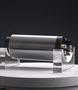
Technical requirement of Yaw and Pitch bearings for wind turbine:
The width of the soft belt of the yaw and pitch slewing bearing should not be greater than the diameter of the plunger hole plus 35mm. The soft belt should generally be placed in the raceway position of the plunger hole.
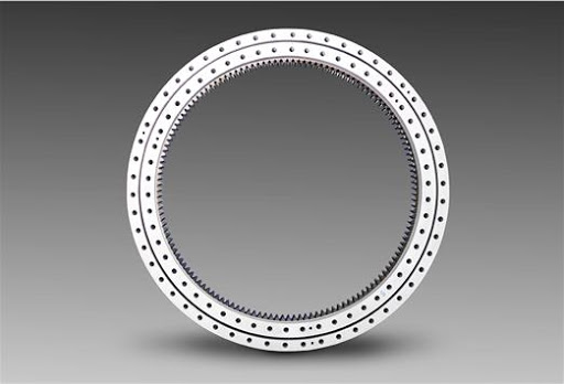
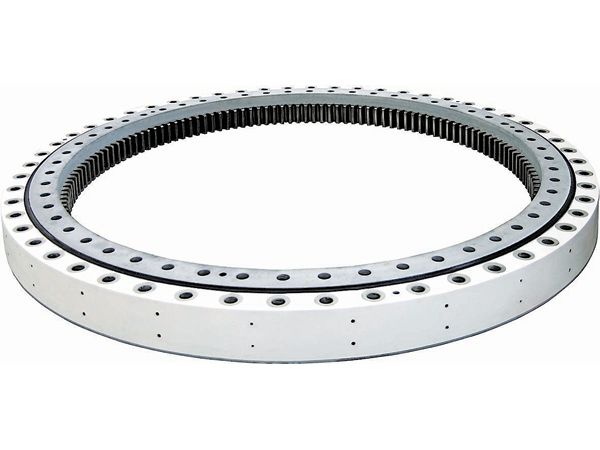
2. Ring gear of the yaw and pitch slewing bearing
Ring gear in the yaw and pitch slewing bearing is mainly involute cylindrical gear with gear radial modification coefficient X=+0.5. Gear module should meet the regulations in GB/T1357-1987 standard. The accuracy of gear should not be lower than the requirements of 998GK in GB/T10095.1-2001 regulations.
3. Clearance
Generally the radial and axial clearance of yaw bearing is 0-50μm, and the clearance can be adjusted according to the customer requirements.
The radial and axial clearance of pitch bearing is lower than 0.
4. Lubricating oil hole
The yaw bearing and pitch bearing are lubricated through lubricating oil hole, which is screw hole with the specification of M10×1.
5. Seal
For the yaw bearing and pitch bearing in wind turbines, the seal generally use NRB material which comply with HG/T2811-1996. ZYS uses the sealing ring of well-known foreign brands with good performance and reliable quality for our yaw bearing and pitch bearing.
Because the wind turbine is exposed to the wild, there are strict requirements on the sealing performance of the yaw bearing and pitch bearing, and the seal form of the bearing must be optimized to ensure that the bearing life is the same as the wind turbine. Wind turbine are installed at an altitude of more than 50m or even hundreds of meters, and the cost of assembly and disassembly is expensive. Therefore, they must have very high reliability. Generally, they require 20 years of life. In addition, the bearing structure is complicated, so the requirements for design and manufacture of yaw bearing and pitch bearing are extremely high.
6. Spacer and cage
7. Preservative treatment
For the yaw bearing and pitch bearing, all surfaces except the groove and gear should be applied thermal spraying anti-corrosion treatment according to the regulations in GB/T9793-1997 and GB/T8427-1996. When applied zinc coating, the thickness of anti-corrosion layer shall be no less than 160μm. Other anti-corrosion treatment can be applied to meet the performance requirements of the machine.
Basic code | Dimension of single row four point contact ball slewing bearing | Gear parameter | External gear | Internal gear | |||||||||||||
Without gear | Outer gear | Inner gear | D | d | T | D1 | d1 | dn | n | H | h | b | m | Da | Z | da | z |
010.30.560 | 011.30.560 | 013.30.560 | 662 | 458 | 80 | 626 | 494 | 18 | 20 | 70 | 10 | 60 | 5 | 689 | 135 | 427 | 86 |
010.30.560 | 012.30.560 | 014.30.560 | 662 | 458 | 80 | 626 | 494 | 18 | 20 | 70 | 10 | 60 | 6 | 688.8 | 112 | 428.4 | 72 |
010.30.630 | 011.30.630 | 013.30.630 | 732 | 528 | 80 | 696 | 564 | 18 | 24 | 70 | 10 | 60 | 6 | 772.8 | 126 | 494.4 | 83 |
010.30.630 | 012.30.630 | 014.30.630 | 732 | 528 | 80 | 696 | 564 | 18 | 24 | 70 | 10 | 60 | 8 | 774.4 | 94 | 491.2 | 62 |
010.30.710 | 011.30.710 | 013.30.710 | 812 | 608 | 80 | 776 | 644 | 18 | 24 | 70 | 10 | 60 | 6 | 850.8 | 139 | 572.4 | 96 |
010.30.710 | 012.30.710 | 014.30.710 | 812 | 608 | 80 | 776 | 644 | 18 | 24 | 70 | 10 | 60 | 8 | 854.4 | 104 | 571.2 | 72 |
010.40.800 | 012.40.800 | 014.40.800 | 922 | 678 | 100 | 878 | 722 | 22 | 30 | 90 | 10 | 80 | 10 | 968 | 94 | 634 | 64 |
010.40.900 | 011.40.900 | 013.40.900 | 1022 | 778 | 100 | 978 | 822 | 22 | 30 | 90 | 10 | 80 | 8 | 1062.4 | 130 | 739.2 | 93 |
010.40.900 | 012.40.900 | 014.40.900 | 1022 | 778 | 100 | 978 | 822 | 22 | 30 | 90 | 10 | 80 | 10 | 1068 | 104 | 734 | 74 |
010.40.1000 | 011.40.1000 | 013.40.1000 | 1122 | 878 | 100 | 1078 | 922 | 22 | 36 | 90 | 10 | 80 | 10 | 1188 | 116 | 824 | 83 |
010.40.1000 | 012.40.1000 | 014.40.1000 | 1122 | 878 | 100 | 1078 | 922 | 22 | 36 | 90 | 10 | 80 | 12 | 1185.6 | 96 | 820.8 | 69 |
010.40.1120 | 011.40.1120 | 013.40.1120 | 1242 | 998 | 100 | 1198 | 1042 | 22 | 36 | 90 | 10 | 80 | 10 | 1298 | 127 | 944 | 95 |
010.40.1120 | 012.40.1120 | 014.40.1120 | 1242 | 998 | 100 | 1198 | 1042 | 22 | 36 | 90 | 10 | 80 | 12 | 1305.6 | 106 | 940.8 | 79 |
010.45.1250 | 011.45.1250 | 013.45.1250 | 1390 | 1110 | 110 | 1337 | 1163 | 26 | 40 | 100 | 10 | 90 | 12 | 1449.6 | 118 | 1048.8 | 88 |
010.45.1250 | 012.45.1250 | 014.45.1250 | 1390 | 1110 | 110 | 1337 | 1163 | 26 | 40 | 100 | 10 | 90 | 14 | 1453.2 | 101 | 1041.6 | 75 |
010.45.1400 | 011.45.1400 | 013.45.1400 | 1540 | 1260 | 110 | 1487 | 1313 | 26 | 40 | 100 | 10 | 90 | 12 | 1449.6 | 118 | 1048.8 | 88 |
010.45.1400 | 012.45.1400 | 014.45.1400 | 1540 | 1260 | 110 | 1487 | 1313 | 26 | 40 | 100 | 10 | 90 | 14 | 1607.2 | 112 | 1195.6 | 86 |
010.45.1600 | 011.45.1600 | 013.45.1600 | 1740 | 1460 | 110 | 1687 | 1513 | 26 | 45 | 100 | 10 | 90 | 14 | 1817.2 | 127 | 1391.6 | 100 |
010.45.1600 | 012.45.1600 | 014.45.1600 | 1740 | 1460 | 110 | 1687 | 1513 | 26 | 45 | 100 | 10 | 90 | 16 | 1820.8 | 111 | 1382.4 | 87 |
010.45.1800 | 011.45.1800 | 013.45.1800 | 1940 | 1660 | 110 | 1877 | 1713 | 26 | 45 | 100 | 10 | 90 | 14 | 2013.2 | 141 | 1573.6 | 113 |
010.45.1800 | 012.45.1800 | 014.45.1800 | 1940 | 1660 | 110 | 1877 | 1713 | 26 | 45 | 100 | 10 | 90 | 16 | 2012.8 | 123 | 1574.4 | 99 |
010.60.2000 | 011.60.2000 | 013.60.2000 | 2178 | 1825 | 144 | 2110 | 1891 | 33 | 48 | 132 | 12 | 120 | 16 | 2268.8 | 139 | 1734.4 | 109 |
010.60.2000 | 012.60.2000 | 014.60.2000 | 2178 | 1825 | 144 | 2110 | 1891 | 33 | 48 | 132 | 12 | 120 | 18 | 2264.4 | 123 | 1735.2 | 97 |
010.60.2240 | 011.60.2240 | 013.60.2240 | 2418 | 2065 | 144 | 2350 | 2131 | 33 | 48 | 13 | 12 | 120 | 16 | 2492.8 | 153 | 1990.4 | 125 |
010.60.2240 | 012.60.2240 | 014.60.2240 | 2418 | 2065 | 144 | 2350 | 2131 | 33 | 48 | 13 | 12 | 120 | 18 | 2498.4 | 136 | 1987.2 | 111 |
010.60.2500 | 011.60.2500 | 013.60.2500 | 2678 | 2325 | 144 | 2610 | 2391 | 33 | 56 | 132 | 12 | 120 | 18 | 2768.4 | 151 | 2239.2 | 125 |
010.60.2500 | 012.60.2500 | 014.60.2500 | 2678 | 2325 | 144 | 2610 | 2391 | 33 | 56 | 132 | 12 | 120 | 20 | 2776 | 136 | 2228 | 112 |
010.60.2800 | 011.60.2800 | 013.60.2800 | 2987 | 2625 | 144 | 2910 | 2691 | 33 | 56 | 132 | 12 | 120 | 18 | 3074.4 | 168 | 2527.2 | 141 |
010.60.2800 | 012.60.2800 | 014.60.2800 | 2987 | 2625 | 144 | 2910 | 2691 | 33 | 56 | 132 | 12 | 120 | 20 | 3076 | 151 | 2528 | 127 |
010.75.3150 | 011.75.3150 | 013.75.3150 | 3376 | 2922 | 174 | 3286 | 3014 | 45 | 56 | 162 | 12 | 150 | 20 | 3476 | 171 | 2828 | 142 |
010.75.3150 | 012.75.3150 | 014.75.3150 | 3376 | 2922 | 174 | 3286 | 3014 | 45 | 56 | 162 | 12 | 150 | 22 | 3471.6 | 155 | 2824.8 | 129 |
010.75.3550 | 011.75.3550 | 013.75.3550 | 3776 | 3322 | 174 | 3686 | 3414 | 45 | 56 | 162 | 12 | 150 | 20 | 3876 | 191 | 3228 | 162 |
010.75.3550 | 012.75.3550 | 014.75.3550 | 3776 | 3322 | 174 | 3686 | 3414 | 45 | 56 | 162 | 12 | 150 | 22 | 3889.6 | 174 | 3220.8 | 147 |
010.75.4000 | 011.75.4000 | 013.75.4000 | 4226 | 3772 | 174 | 4136 | 3864 | 45 | 60 | 162 | 12 | 150 | 22 | 4329.6 | 194 | 3660.8 | 167 |
010.75.4000 | 012.75.4000 | 014.75.4000 | 4226 | 3772 | 174 | 4136 | 3864 | 45 | 60 | 162 | 12 | 150 | 25 | 4345 | 171 | 3660 | 147 |

WIND ENERGY